2 required: 63mA 250VA at 60Hz, or 100mA 250VA at 50Hz
Supply voltage
120 or 240VAC
-15% to +10%
15VA at 50Hz, or 12VA max. at 60Hz
Signal input
IR & UV signals from scanner head
Flame on response
1s max.
Flame failure response time (FFRT)
0.5 to 3.5s (independent for UV and IR)
+/- 0.5s adjustable with 0.5s increments
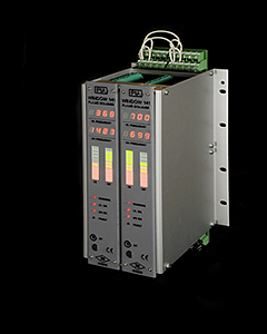
Display
Two digital displays: one for IR flicker frequency and one for UV frequency proportional to intensity.
Two multicolour LED bar graphs: one for IR relative frequency and one for UV relative intensity.
System status LEDs.
Chassis
Chassis available in different sizes, which can accommodate from 1 to 8 signal processing modules.
Output contacts
Individual UV, IR flame (NO) relay and system fault relay connected to your burner management system.
Relay contact ratings:
Max. switching power: 60W / 125VA
Max. switching voltage: 220VDC / 250VAC
Max. switching and carrying current: 2A
Analog output
0 or 4 to 20mA, representing the highest IR or UV bar graph level.
Maximum 500 ohms load resistance between output and -12VDC.
Adjustment and verification
Digital. No potentiometer for flame sensitivity adjustment required.
A
handheld terminal
unit permits adjusting and verifying the system.
False signal rejection
Automatic rejection of any constant (for 8s or more) IR and/or UV signal which does not represent a real flame (incandescent light, interference, defective UV tube, etc.), and activation of the system fault relay.